Microcontroller evaluation: A year of hardware challenges
Dec 13 2025
At the beginning of this year I purchased a few Rasberry Pi Pico 2s and I had some projects in mind that I wanted to build, and had determined that would be a good microcontroller for them, especially from an ease-of-use standpoint. I had never used a Pico before so I knew there would be a learning process. I purchased the Rasperry Pi Debug Probe as well to use for this and future projects.
I was quite rusty with microcontroller programming in C so this served as a good refresher. My past experience was with the Atmel AVR architecture.
I had several different hardware devices I wanted to test out from the Pico:
- A DS3231 RTC module
- Two LCDs with 1602 backpacks
- An HS-311 servo. The default character of servos. The F-150 of servos. The Cessna 172 of servos. (Though I later realized I should have been buying the HS-318 which is the 25 tooth version, which is what most 3rd party horns use)
- An incremental encoder
- A Bourns absolute encoder (
EMS22A30-C28-LS6)
The last but most complex concept I wanted to test was communicating between a Rasberry Pi (running Rust) and the Pico using SPI. I wanted to really examine how to implement this because it is a key component of one of my future projects.
I had gotten very excited about the Pi Pico 2. I was planning to use it as my main microcontroller for several planned future projects. I designed and 3D printed a custom evaluation setup for the Pico. It integrated all the components I wished to evaluate into an fixed enclosure to help keep the mess at least somewhat organized:
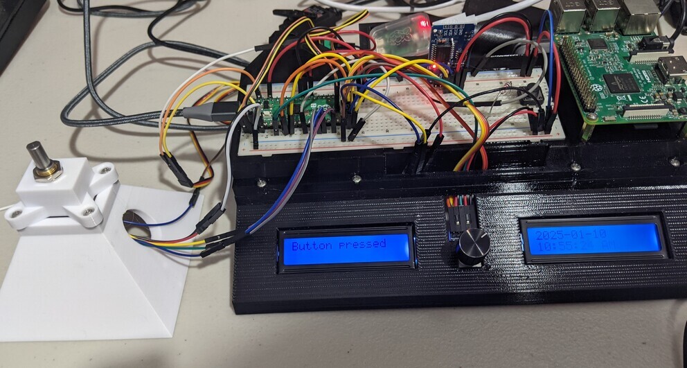 Check out the "Pyramid of Absolute Encoder"!
As part of the process of building this I also started to work on crimping as well, another skill I would need for these new projects. Its a surprisingly confusing world of all sorts of different standardized connectors, knockoffs, official crimpers (that no hobbyists use) and third party crimpers (that hobbyists use and vastly disagree about which ones perform best for which connector types). Based on its use as Adafruit's STEMMA and its relatively compact size, I had settled on JST PH as my primary board-to-board connector for my own custom designs when data/low voltages are involved.
This turned out to be quite helpful as the pitch of JST PH happens to align perfectly with the pins on the absolute encoder, so I was able to crimp my first connector for it, going from JST PH on one side to 1 pin male DuPont connectors on the other side.
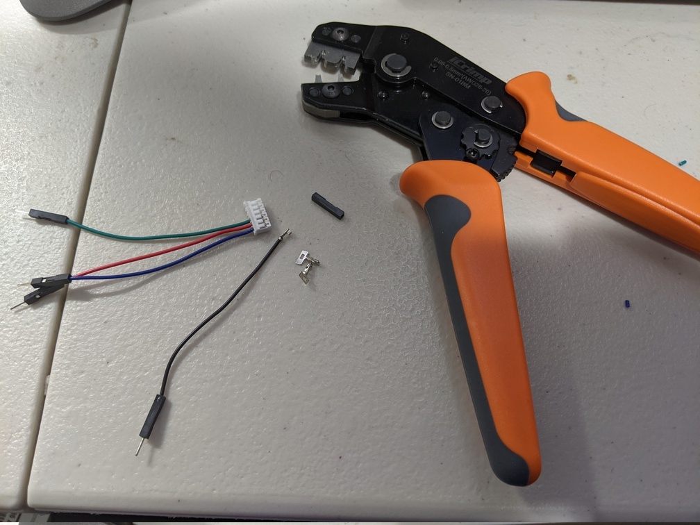
I found that the SN-01 crimper worked decently, though much later down the line I would switch to the Engineer PA-09. If there is one lesson I've learned over this past year its that the two-step crimpers are superior to the crimpers that attempt to perform crimping of the insulation and conductor in the same step.
I was able to successfully integrate and run all the above listed hardware using the Pico 2. I had gotten pretty far along at this point! I programmed it so I could set the position of the servo using the absolute encoder:
But then I got to the last step: SPI from a Pi 5 to the Pico 2. This leads us to:
SPI on the Pico is broken
(At least as a slave device)
Others online seem to concur: "rp2040 SPI peripheral is fundamentally broken in every possible regard, at least when you're trying to implement a slave device. On top of it there's a very raw driver in the SDK which introduces another layer of brokedity."
It was a nightmare trying to get my Pico to receive bytes. I tried so many different things. I bypassed the SDK spi_read_blocking command and read from the data register directly. I learned from this discussion and the datasheet (see page 1051) that in mode 0, the Pico (or, more accurately, the PrimeCell SSP) requires the CS pin to be toggled after every byte sent. Otherwise no bytes after the first byte will be received and made available in the data register. One solution is to use mode 1, which does allow multiple bytes to be received.
Once I had that figured out and switched to mode 1, I then struggled with only ever being able to receive the first 8 bytes of the message from the SPI slave, which happens to be the FIFO depth of the Pico. This turned out to be a speed issue, I had to slow the clock down a ton to ensure the register didn't fill before I could read from it.
It had been many, many days of frustration at this point. However, I had something that "semi-worked." But there were frequent issues with bit shifts causing loads of misinterpreted data being pushed into the data register. As I do need high speed transmission, this meant that my current solution was unfeasible, as I would have to constantly be correcting these bit shifts. After spending so much time on this problem with such mediocre progress, I was feeling pretty fed up with the Pico, and was frustrated as I had planned out multiple projects with the Pico in mind. After some consideration, I decided that because SPI communication was so fundamental to what I wanted to do, I would switch to an STM32 which is a much more well developed and mature product. It had been my initial choice before I saw the Pico, which seemed to be easier to use since I wouldn't need to build my own custom PCB for it. But at this point I had already decided to use a custom PCB for the Pico anyways, so why not go back to STM32? I knew that making a good circuit design for the actual microcontroller-specific components can be complex, but I surely I can figure it out, right?
This did mean starting all over with a brand new evaluation project. And learning how to work with STM32 programming, which is all new to me. I picked up a Segger J-Link debugger and - with some frustration - threw all my Pico hardware in a box. On the plus side because I had already been considering it, I had a Nucleo development board sitting around that I could immediately start testing things with.
In the next post I'll talk more about the process of designing an STM32 eval board to test the same hardware used for the Pico evaluation.
Comments