Cat-Controlled Cat Feeder
May 01 2021
Concept

This cat is a bit of an asshole. Her name is Blondie. Look at those cold, unblinking eyes. No really, I don’t think she ever blinks. She waits until the worst possible moments to be annoying. The only thing she loves more than anger and violence, is food. She is rarely ever cuddly, choosing instead to stare at you wide-eyed from a comfortable distance. I have never met a cat quite like this. It clearly, plainly, obviously follows that I must design something in order to face off against her attitude. I must bring my own weapon to this battle: mind games. As food is her primary motivator, it makes sense to use food as the medium for these mind games.
I then chose what I wanted to design: An automated cat feeder. “A cat feeder doesn’t seem like much of a weapon of psychological warfare...” you say (I assume). Thats true. However, this is not just a standard cat feeder that simply spits out food at regular intervals. Those are widely available, and cheap too. What I am building here is a cat controlled cat feeder. The cat must tell the machine to give her food. Then once the cat learns of her new magical ability to summon food at will, I can begin choosing when and how that power is granted.
While I’d like to implement a 3D-printed auger-based design at a future point, I figured an existing feeder would be a good starting point, specifically this Automatic Feeder. Like many products on Amazon, its brand name seems to change monthly. Customers on Amazon clearly love this thing based on the 4.5 star score after over 3600 ratings at the time of writing. By default this device is designed to regularly dispense food, quickly teaching your cat to lose its mind every time that little motor starts to buzz. It seems perfectly adequate to turn into a cat-activated system, however a major downside is that the feeder uses a simple paddle system at the base of the hopper.
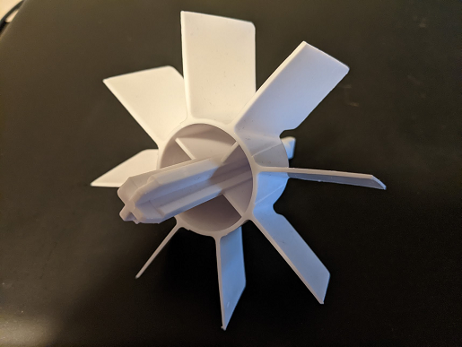
This system is intented to provide a specific amount of food (the amount that fills the space between two paddles), and the motor is designed to rotate until the space between two paddles is completely emptied into the bowl. Ideally, for precise control, one would want a system where a constant flow of food would be dispensed as the motor spins. Hence why if I were to build an improved version of this, I would use a custom built auger system. I made all the STL files for such a project, but wanted to build this first so I wasn't bogged down in the hardware portion of the project (which, in my experience, is usually the biggest stopping point. Oh how I'd love to have my own workshop so everything didn't always feel so hacky.) On the plus side, this feeder comes with a swappable "paddle wheel" in two sizes, so I installed the small size. Pictured is the large one that was removed.
The feeder comes with its own little control unit, which is the primary thing I am replacing. So the first step was to learn what wires did what. I grabbed my multimeter, and measured the voltage at each point, using the “manual activation” button on the existing control unit. 5 volts control for motor. Perfect! The Raspberry Pi already has a 5v voltage source. (I wish I had more photos here but I'm afraid I didn’t take many during this process)
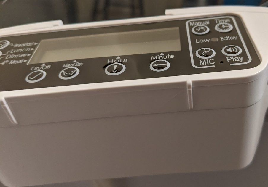
There were two yellow wires running from the motor to the control unit. I noticed that there is a “click” noise as the motor rotates, definitely at an even interval. I also observed that on the first click, the voltage across these two yellow wires is whatever input voltage is given to it. On the second click, the voltage drops to zero. Short circuit. So the yellow wires are connected to a switch that is mechanically activated by the rotation of the motor, allowing the control unit to identify when a single unit of food has been dispensed. Seeing as this may come in handy, this was factored in to my design.
I then ripped out (gently removed) the control unit. Its garbage. Its useless. Get it out of here. The Raspberry Pi is in charge now
Control Circuit Design
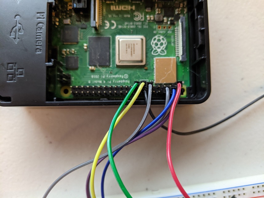
The control for the motor would be pretty simple: use a 3.3v logic output from the GPIO to control a relay that opened/closed circuit to the motor. The power on the other end of said circuit would be from the 5v source provided on the Raspberry Pi. When I say “relay” here what I mean is a relay module, as I don’t want the sensitive GPIO pins exposed directly to a relay without any protection from diodes and whatnot.
Below is the actual schematic I used as my reference when assembling the circuit. Witness my amazing MS Paint skills!

I mostly stuck to the color code of the actual wires coming out of the feeder. Recall from earlier that the yellow lines are the feedback from the internal switch. The pull-up resistor (drawn horizontally leading to the switch/button) I decided to solder inside of the button instead of attaching it to the control circuit. Also I don't think the "switch lamp" was ever implemented, I just have an LED tied to the relay to show when it activates (or at least should be activating).
The Button
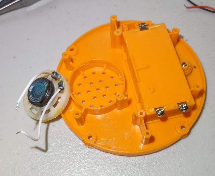
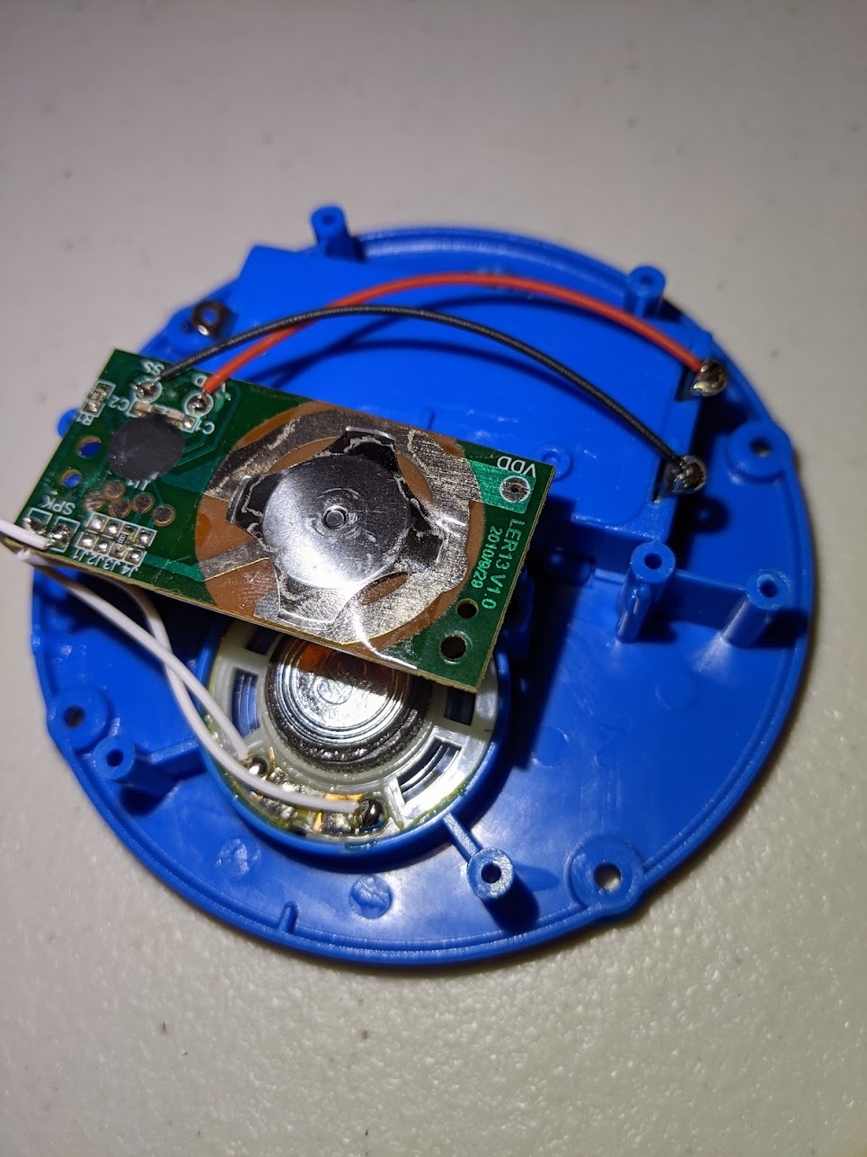
For the button input to the Pi, I needed something that a cats paw could pretty easily press. Inspired by Billi and seeing how easily she is able to use those big plastic buttons, I bought these little “game show buzzers” intended for use as a teaching tool for kids. I appreciated they came in a pack of 4 so I could comfortably destroy one or two to get an idea of how it is put together and what I need to solder to in order to have it work as a digital input for the feeder.
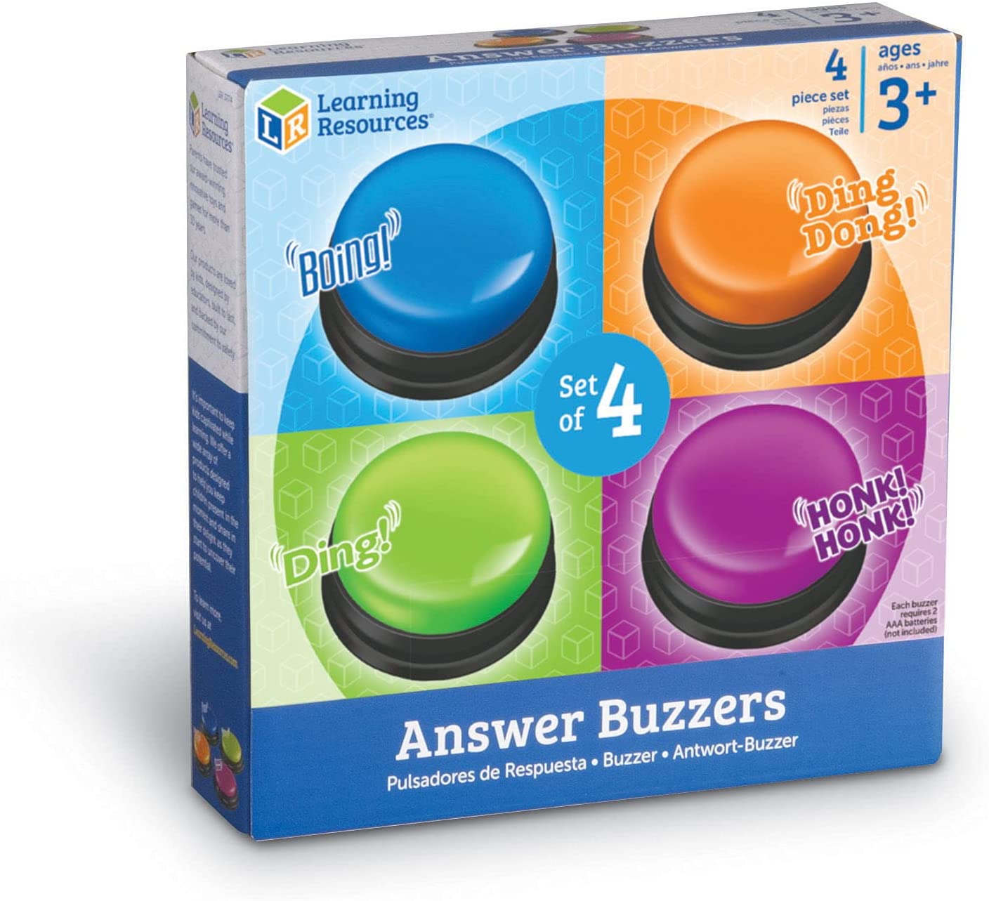
The color of the pictured buttons changes as I took the photos while working will multiple buttons, but they are all copies of each other.
Removing the speaker so I can access the holes through which I'll run wires:
Original button cicruitry after removing the top half:
The switch and circuit:
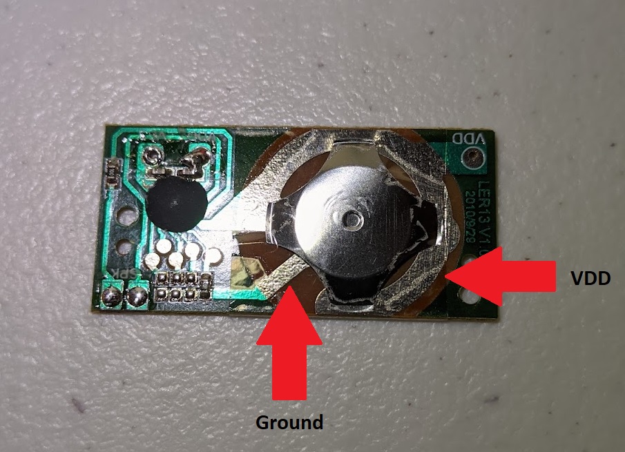
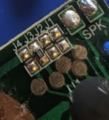
On my first attempt at rewiring this to work as a simple switch, it kept refusing to change from 1 to 0 when I tested it with a Pi. After some inspection with a multimeter I discovered that both sides of the switch are connected by a 7.5MΩ resistance. Through process of elimination (desoldering components from the board), I discovered the source of the issue. As seen above, the button comes in a pack of 4 and each one makes its own unique sound. Also note that there are 4 junctions lined up (labelled J1, J2, J3, J4). Those junctions, I assume, cause the button to trigger a specific sound when joined together through that resisor. Desoldering that resistor removed any connection on the circuit between ground and VDD.
Completed switch circuit. Not beautiful but it works:
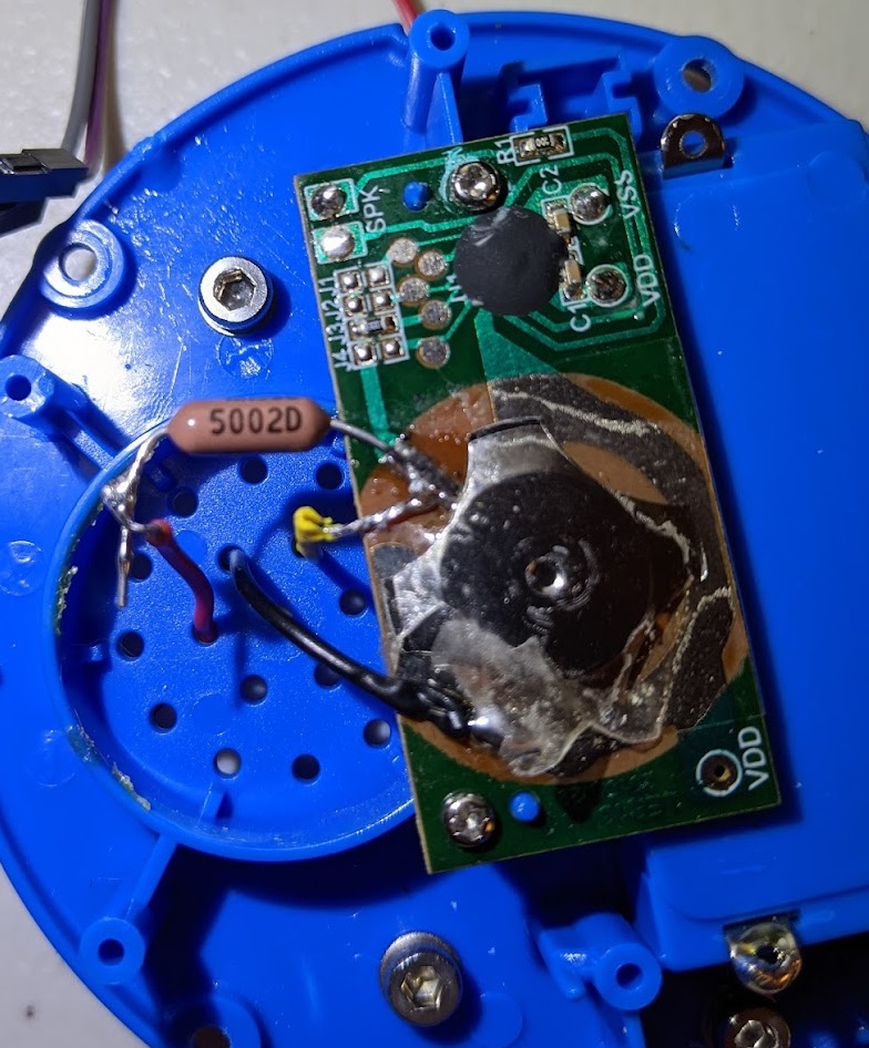
I don’t know if this would be considered “good practice” but when I need 4 or fewer conductors over some distance, I like to use 3.5mm audio cables to accomplish this task. The screw terminal breakouts for them are readily available on Amazon and are very pleasant to work with, and the cables are cheap and available in almost any combination of conductors and end types you could imagine. Since I only need 3 conductors for the button, I went ahead and used 3.5mm cable for connecting the button to the Pi.
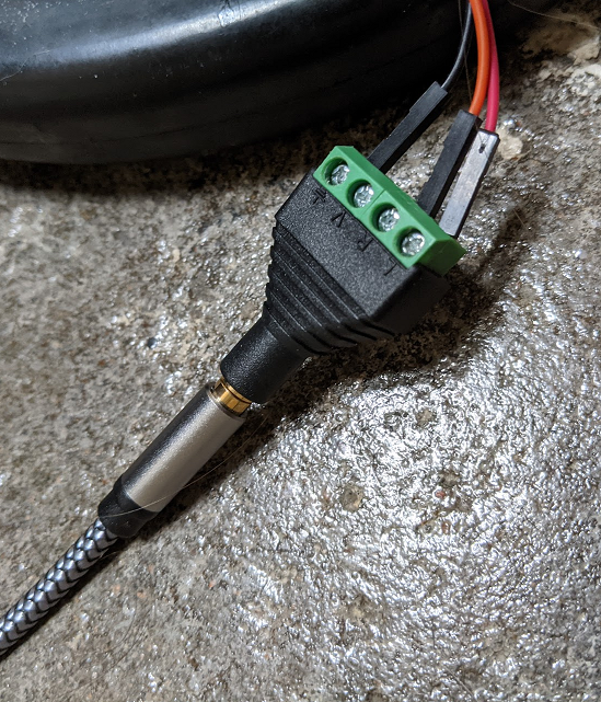
Having a cable like this is also great for when I want to move the button further away from the feeder so the cat must always travel between the button and the food. I always appreciate an opportunity to demand more effort from the lazy feline.
Software/UI
Now that the hardware side is pretty much squared away (though still on breadboards), its time for the software. I don’t simply want the button to run the motor, I want inputs and output managed by a variety of customizable options. Hence why it is called a “configurable cat feeder”. Since gpiozero is a really convenient library I decided to build the whole thing in Python. It is built around a server, so that any system on the network can configure the feeder. I used aiohttp for the server code and used asyncio itself as well to inject my own asynchronous functions into the server (so that button presses along with server sessions are all handled by the same event loop).
# in server class init
self.cat_button = Button(22)
self.cat_button.when_pressed = self.cat_button_pressed

# server class method
def cat_button_pressed(self):
    def cat_button_pressed_internal():
        db_con = db_connection()
        self.handle_button_press(db_con)
    # pressing the physical button adds this callback into
    # the same event loop that the server uses
    self.loop.call_soon_threadsafe(cat_button_pressed_internal)
Since I needed access to the same event loop being used by the server, instead of using aiohttp's built-in "web.run_app" method I manually initialized the asyncio event loop and started the server
# in server class init
runner = web.AppRunner(app)
self.loop = asyncio.new_event_loop()
asyncio.set_event_loop(self.loop)
self.loop.run_until_complete(runner.setup())
site = web.TCPSite(runner,host,port)
self.loop.run_until_complete(site.start())
print('Running server on http://'+host+':'+str(port))
self.loop.run_forever()
To reset the "remaining dispenses" number every day, I made a seperate Python script, and then used crontab to run it daily. Initially I had it reset at midnight, but switched to the early morning so that Blondie was pretty calm and satisfied at the start of the day.
This script also shifts the "feeding window" which at the moment I don't use (shift is at 0, feeding window is all day)

A screenshot of the user interface is shown below. Each "update" button simply sends a post request to the server, which updates the associated parameter. Yes its ugly but I thought the imagery was funny.
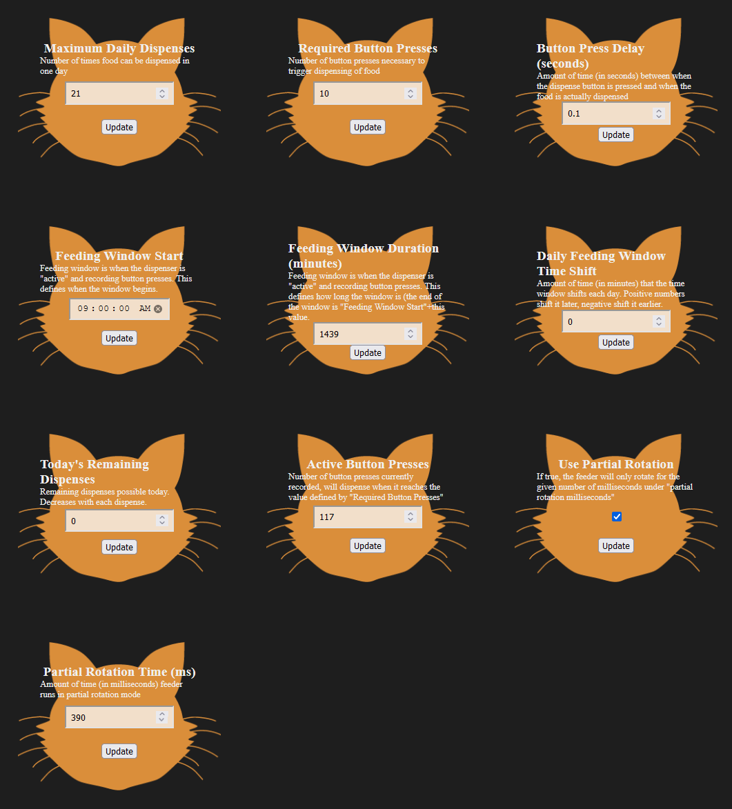
This screenshot also gives you the opportunity to look at all the parameters currently implemented by the feeder. There are a lot of options that can be precisely tweaked. Note how the "active button presses" is at 117, even though required button presses is 10. The greedy cat has already used up her days supply of food, and now is just pressing the button in desperation. I think this means victory.
Note: I have had to drop the max dispenses quite a bit because she has been getting too fat as I let her become very familiar with the button. When I first started, that value was just set to 9999
Training the Cat
My girlfriend helped quite a bit with this part, as she is experienced with training animals. I showed her some videos of people training their cats to ring a bell for food, and initial training was inspired by them. Instead of having the feeder run when she pressed the button, we gave her food every time she touched the button. We then progressed to feeding her only when she touched the top of the button. She caught on to that pretty quickly, but she seems to have an inclination not to “press” but to “swipe.” (Disregard the beautiful Logitech Marble Mouse back there being used for working directly with the Pi) She would push the button, or she would hit the side of the button instead of the top.
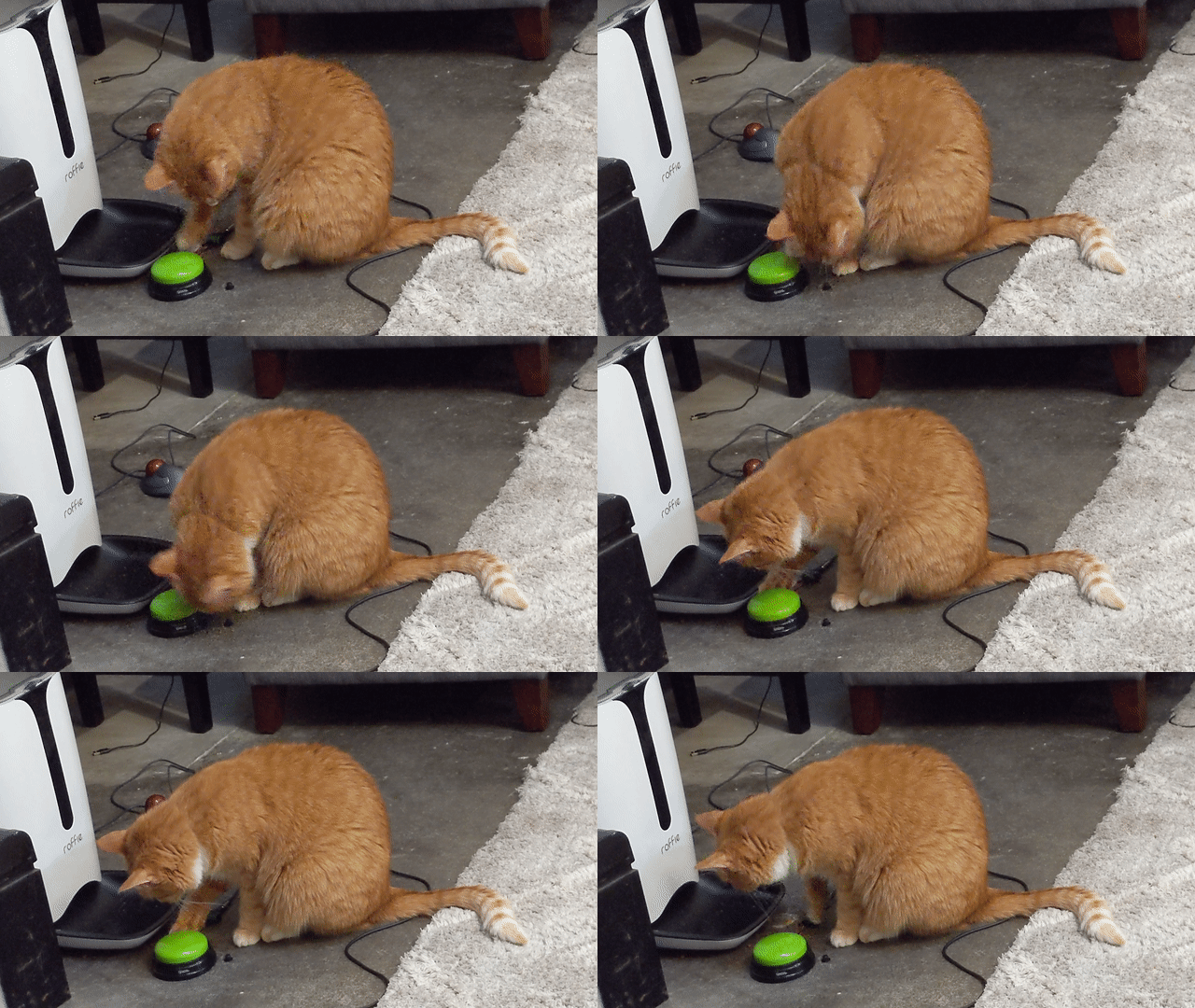
Maybe she will attack the mouse? (The bits on the bowl are from wet food my girlfriend put out for the cat as a reward earlier):
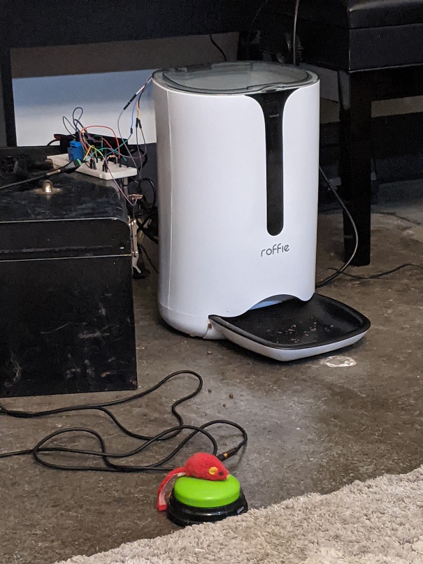
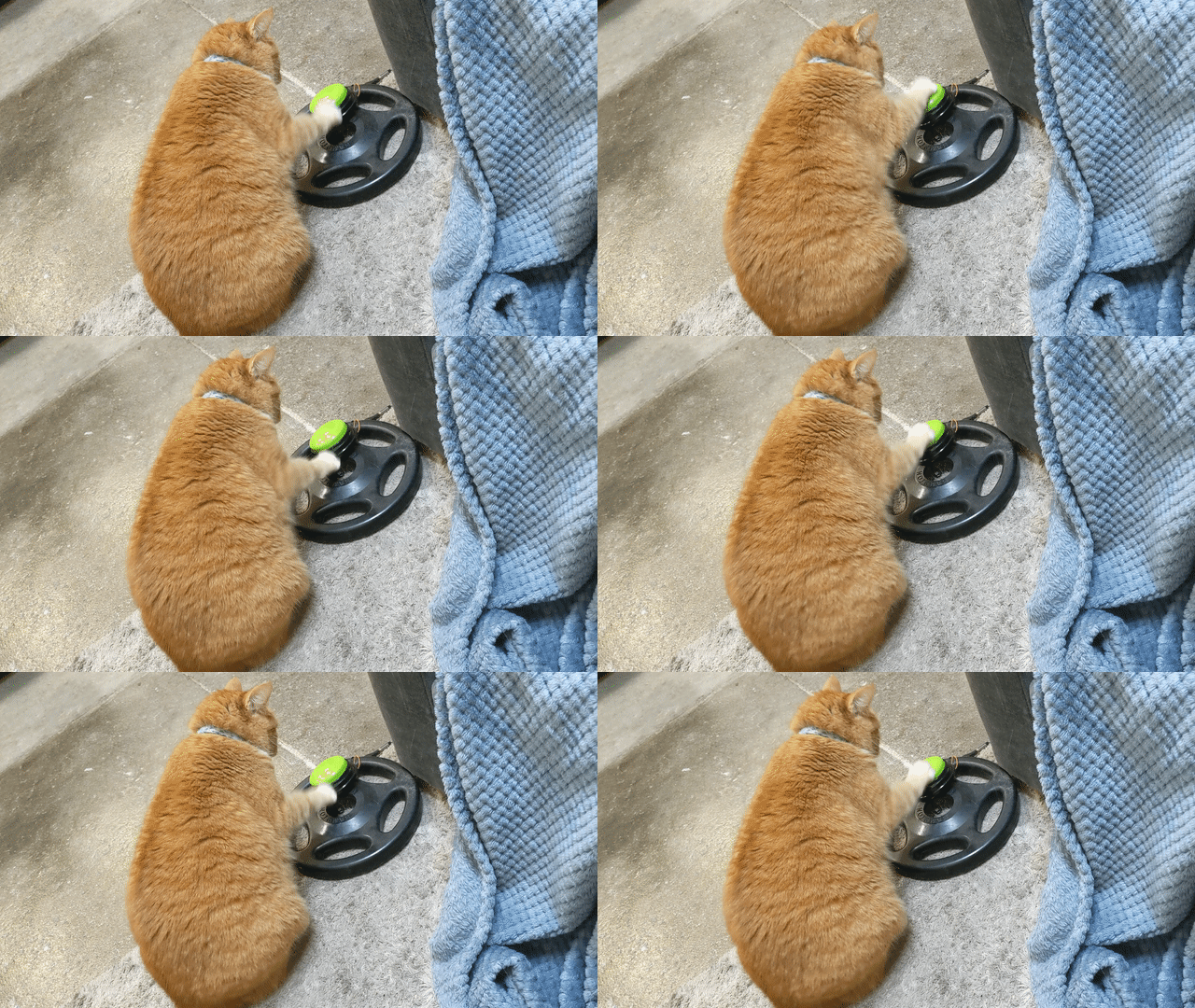
The final piece of the puzzle that got Blondie to figure out how to use the button was the purchase of a laser pointer. By having the feeder set up to run once per button press, if we could lead her to chase the laser to the button, she would activate it with a slap and receive food. She caught on very quickly from that point onward, and soon was pressing the button on her own. I zip-tied the button to a 25 lb weight so she couldn't slide it around, that also helped a great deal.
Recorded several months later:
Soldered Board
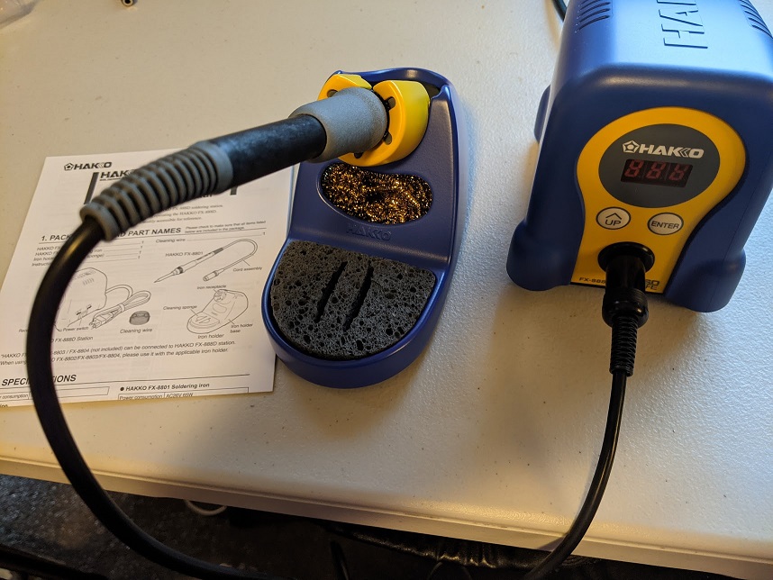
For some reason, the cat has decided that her reaction to the feeder no longer giving her more food (after she runs out of dispenses for the day) is to attack the feeder, pulling it forward far enough to start pulling wires out of the breadboard. So, after many months of using this feeder as a simple breadboard circuit, I have finally decided to make a properly soldered circuit. This also gave me an excuse to finally throw away my ancient cheap RadioShack (yes RadioShack) soldering iron, and pick up a Hakko FX-888D.
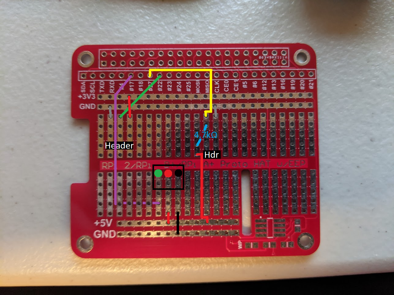
Circuit reference for soldered board:
Enclosure
Blondie likes to attack the feeder sometimes (I think sliding it around has sometimes caused a piece or two of food to fall out so that is what she is trying to make happen). To prevent her from damaging the control circuit, I purchased a project enclosure and drilled holes in it to run power, button input, and feeder output. Using the same type of connector for both input and output? Yep.
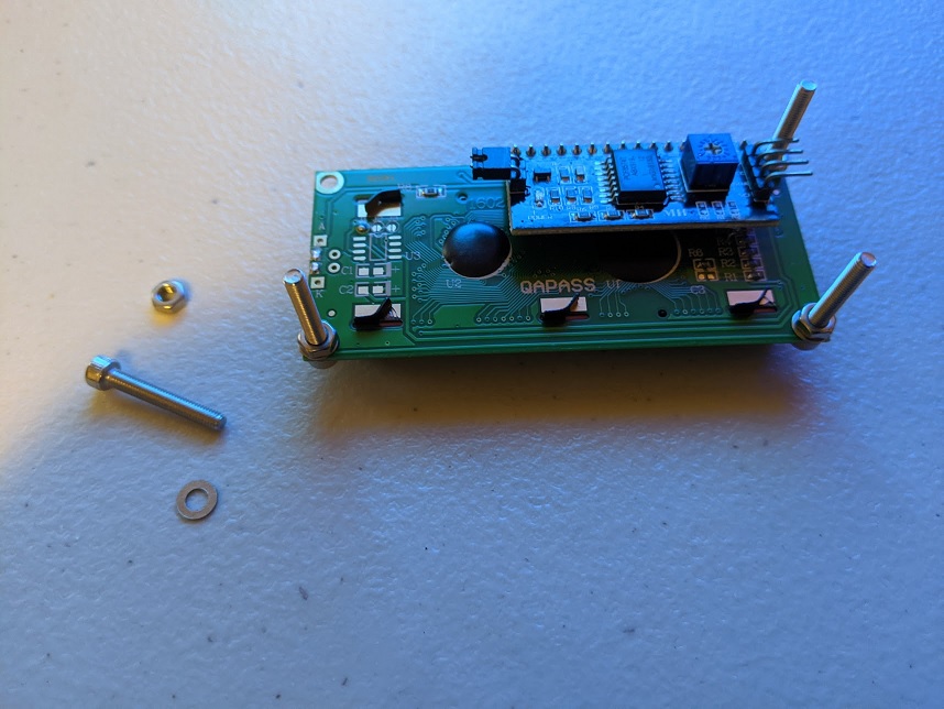
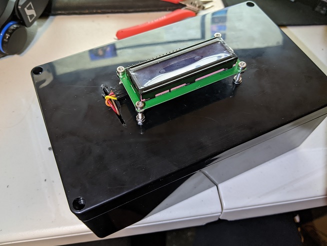
I have tons of M3 screws, nuts, and washers that are great for 3D printed projects, so I figured they would work for mounting the LCD display to the top of the enclosure. I used a dremel to cut a little slot for the 4 wires.
Adding screws to LCD:
Drilled enclosure with LCD mounted:
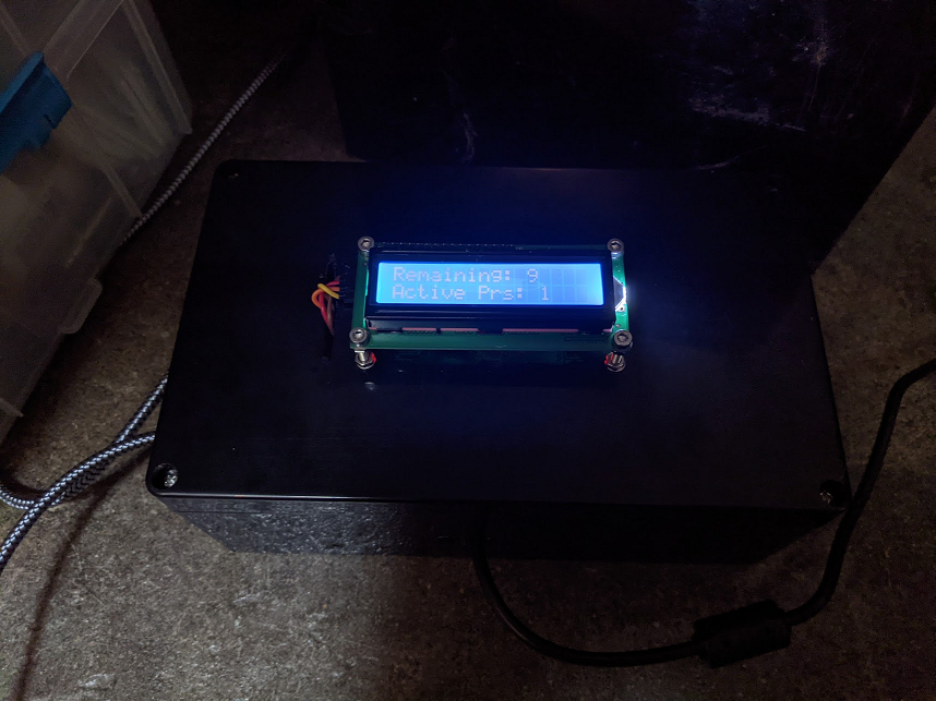
Working control circuit in enclosure:
Comments
No comments yet. Be the first to comment!